E-katalogue
X-ray partition panels 102.08
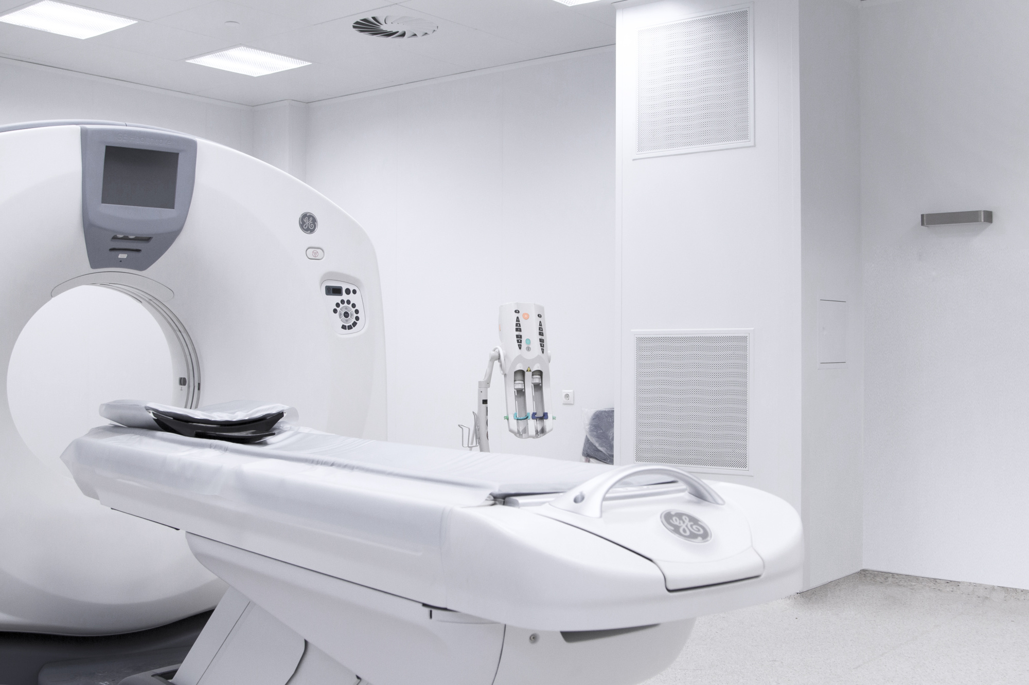
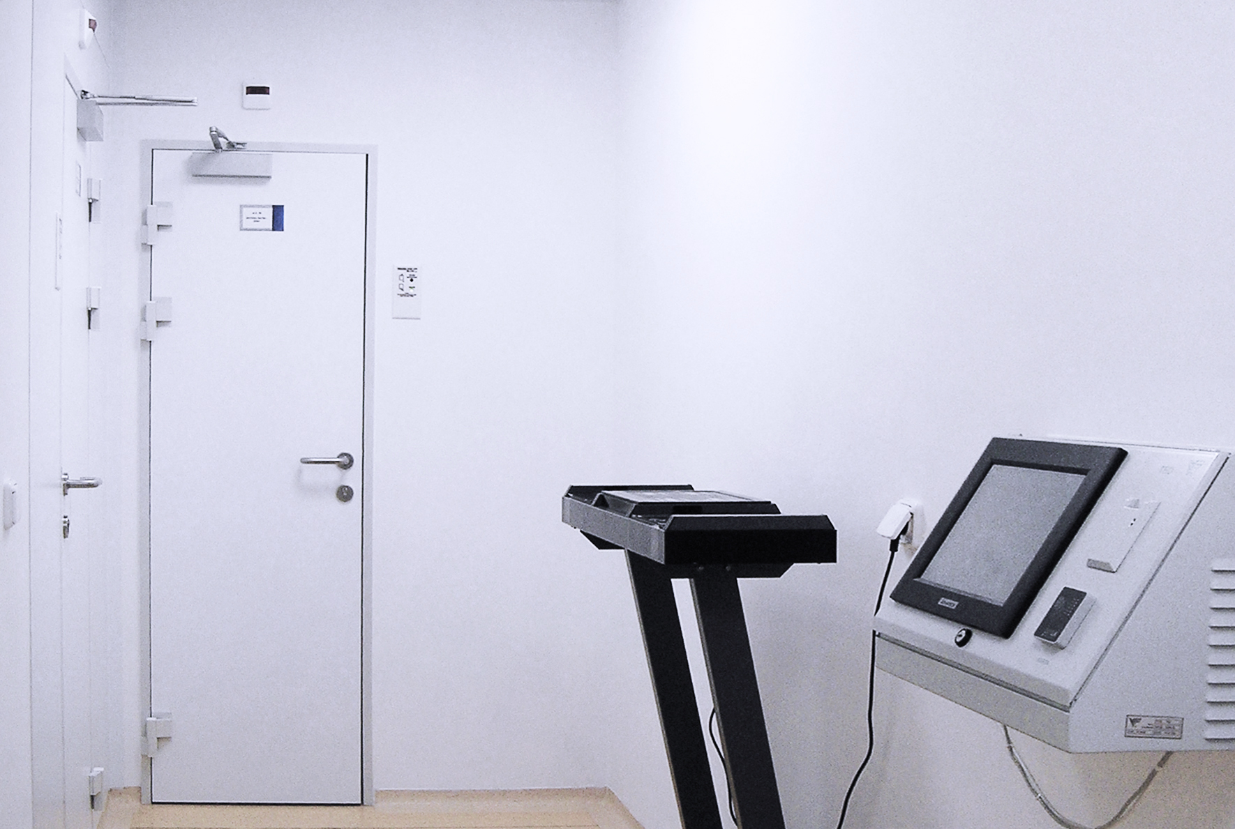
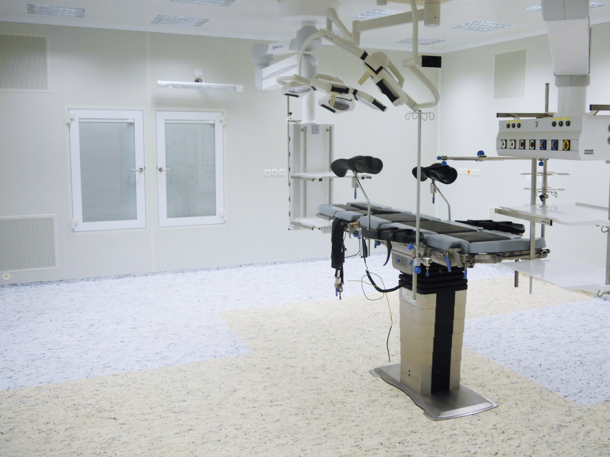
The X-ray partition panel is the main element to construct clean workplaces and areas with protection against X-radiation.
It does not visually differ from standard partition panels. The panels are connected to each other by means of a slide-on connection; a shielding connecting lead insert is inserted in the panel joint which, providing for a perfect overlap of panel joints with the shielded element.
The thickness of the lead shielding insert is always determined by the designer, based on radiation optimisation and radiation limits according to the implementing regulation on radiation protection, in accordance with applicable regulations in each country.
TECHNICAL DATA
| Panel type |
|---|
| Partition panels RTB |
| Thickness of shielding lead insert |
|---|
| 1 mm |
| 1.5 mm |
| 2 mm |
| 3 mm |
| Panel thickness |
|---|
| 100 mm |
| 120 mm |
| 60 mm |
| 80 mm |
| Panel width W | |
|---|---|
| width | value |
| 500 mm | thickness of lead insert 1; 1.5; 2 and 3 |
| 700 mm | thickness of lead insert 1; 1.5 and 2 |
| 900 mm | thickness of lead insert 1 and 1.5 |
| For S2 1 and 1.5: W - width in mm according to dimensional range Preferred dimensions: - max 900 mm For S2 2: W - width in mm according to dimensional range Preferred dimensions: - max. 700 mm. For S2 3: W - width in mm according to dimensional range Preferred dimensions:- max. 500 mmFor a shielding insert with a thickness of 2 and 3 mm, the maximum width is 800 mm. It is possible to order atypical panel dimensions: min. dimension 300 mm, max. dimension 1190 mm. W - width in mm according to dimensional range 500, 700 and 900 mm. | |
| Panel height H |
|---|
| 2550 mm |
| 2750 mm |
| 3050 mm |
| H - height in mm according to dimensional range. Preferred dimensions 2550, 2750, 3050 mm, min. dimension 300 mm, max. dimension 4000 mm. |
| Side end |
|---|
| groove - tongue |
| tongue - tongue |
| groove - straight |
| straight - straight |
| visible HVAC - visible HVAC |
| visible - tongue |
| visible - groove |
| visible HVAC - groove |
| groove - visible HVAC |
| inclined 45° - inclined 45° |
| groove - groove |
| straight - tongue |
| visible HVAC - tongue |
| tongue - visible HVAC |
| visible-groove (max. dimension 1150 mm) |
| Bottom end |
|---|
| basic (tongue) |
| clasic (straight) |
| atypical |
| shielded basic (tongue) |
| Upper end |
|---|
| basic (tongue) |
| basic with reinforcement (tongue) - below windows, above windows |
| clasic (straight) |
| no upper bend (high panels) |
| atypical |
| Side reinforcement |
|---|
| simple reinforcement |
| no side reinforcement |
| right reinforcement, left reinforcement |
| reinforced reinforcement |
| It is necessary to keep the orientation according to the diagram of the side ends. |
| Number of cable glands |
|---|
| cable gland not recommended |
| 2 pcs (1 pc 85 mm from the left - 1 pc 85 mm from the right) |
| cable glands from the right, cable glands from the left |
| Example of designation in the case of multiple cable glands: Orientation and number of cable glands are specified. The first cable gland is 85 mm from the edge. Other cable glands are located 100 mm apart from each other as standard.3;2 – Total of 5 pcs, 3 from the left side+2 from the right side.For atypical designs, it is necessary to specify A-atypical orientation, number. The dimension must be specified in the notes. |
| Filler |
|---|
| mineral wool |
| atypical |
| Facing hue and material - standard on the visible side |
|---|
| galvanized metal sheet, hue RAL 9002 |
| galvanized metal sheet, hue RAL 9016 |
| Stainless steel AISI 304 |
| powder coating (Komaxit), hue RAL |
| Facing hue and material - standard on the rear side |
|---|
| galvanized metal sheet, hue RAL 9002 |
| galvanized metal sheet, hue RAL 9016 |
| Stainless steel AISI 304 |
| Powder coating (Komaxit), hue RAL |
| Attention: It is necessary to always observe the orientation specified in the diagram of the side end S5. |
| Atypical design |
|---|
| Type design |
| Atypical design |
| Type design 0 - Unique specification out of offered versions Atypical design Q - atypical design that cannot be uniquely specified by a code |


